 |
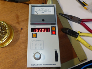
JA5MJW burned his BR-210. Because he turned on his transmitter when he was measureing tunk circit. Probably retern loss bridge (RLB:the most important part of this instrument) might have been broken and out of order. Damage is limitted only in RLB, it will be repaired eazily. But if other parts were damaged, it is hard to repair. |
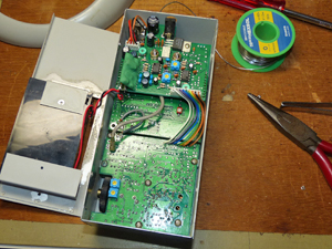
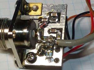
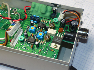
| Opening the device, you can see three print circuit bords(PCB) of display,
oscilator, and frequency counter. RLB bord is directly soldered on M type connector. As the frequency is correctely displyed, oscilator and counter are well working. |
 |
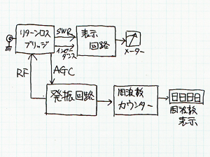 |
I couldn't get the circuit diagram of BR-210 but BR-200 and BR-500 are
available, and it helped me as reference datas. Osclator which is automaticaly lebel contoroled supplys LRB RF power of constant voltage. So BR-210 dosn't have level contorol nob. |
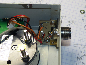
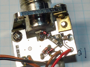
| Remove the display PCB from analog meter, you can see the RLB. Tiny PCB of RLB is soldered directly on the M type connector. Some parts on this bord might have been burned by heigh power RF current. |
 |
 |
 |
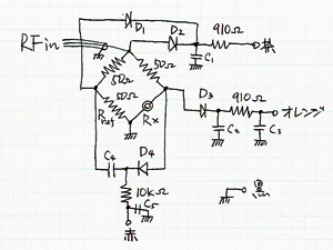 |
I made up a circuit diagram by tracing PCB pattarn. 50 ohm resistors and two diords directly solderd on center condactor of M type conector are considered mostly to be burned. If the 910 ohm and 10k ohm resistors were burned, the disply circuit also might possibly be damaged. |
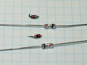
| Checking the parts by circuit tester, I found that D3 and D4 were out
of order. Fortunately, other resisters and diods were not damaged. I replaced D3 and D4 with 1SS16, and rebuild all parts as they had been. |
 |
 |
I measured dummy load for a trial, and found the BR-210 worked well. But, there was a few problems. Perhaps because of the diference of characteristics of replaced diods, I measured errors of SWR by 0.2 at the largest. |
| There were four trimer resisters on PCB. But I couldn't find which were the trimer resisters that must be fixed for adjusting gain and base line of amplifier. |
|
| |
|